
Arduino UNO board explanation
The first step towards learning IoT 💡


Table of contents

No headings in the article.
In this post, I will guide and explain to you the different components of the Arduino board. The reason why I'm writing about Arduino UNO is that it is the most popular board in the Arduino family. In addition, It is the best board to get started with IoT. The components I'm explaining today were the most common once, you get to see them in the majority of the boards.
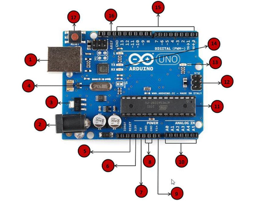
(1) Power USB
Arduino board can be powered by using a USB cable from your computer. All you need to do is connect the USB cable to the USB connection.
(2) Power (Barrel jack)
Arduino board can be powered directly from the AC mains power supply by connecting it to the barrel jack
(3) Voltage Regulator
It is used to control the voltage given to the board and stabilize the DC voltage used by the processor and other elements.
(4) Crystal Oscillator
It is used to deal with time-related issues. It provides a clock signal to microcontroller Atmega 328. This provides a square wave signal which determines the time required for each T state. As in general Arduino board has a 16Mhz frequency crystal hence takes 1/16 sec to run 1 T state.
(5,17) Arduino Reset
You can reset your Arduino board, i.e, start the program from the beginning. There are two ways to reset your board. First, by using the reset button (17) on the board. Second, you can connect an external reset button to the Ardunio pin labelled RESET (5)
(6,7,8,9) Pins
- 3.3V (6) - Supply 3.3 output volt
- 5V (7) - Supply 5 output volt
- Most of the components used with Arduino board works fine with 3.3 volt and 5 volts. *GND (8) Ground - There are several GND pins on the Arduino, any of them can be used to ground your circuit.
- Vin (9) - This pin also can be used to power the Arduino board from an external power source, like AC main power supply
(10) Analog pins
There are six analog pins A0 to A5. Those pins can read the signal from an analog sensor like the humidity sensor or the temperature sensor and convert it into a digital value that can be read by the microprocessor.
(11) Main microcontroller
Each Arduino board has its own microcontroller (11). You can assume it as the brain of your board. The main IC (integrated circuit) on the Arduino is slightly different from board to board. The microcontrollers are usually of the ATMEL Company. You must know what IC your board has before loading up a new program from the Arduino IDE. This information is available on the top of the IC. For more details about the IC construction and functions, you can refer to the datasheet.
There are three types of memories,
First is Flash or Program Memory, which is used to store the program in the memory
The second is SRAM (static random access memory), is where the sketch creates and manipulates variables when it runs.
The third is EEPROM, which is a memory space that programmers can use to store long-term information.
(12) ICSP pin
Mostly, ICSP (12) is an AVR, a tiny programming header for the Arduino consisting of MOSI, MISO, SCK, RESET, VCC, and GND. It is often referred to as an SPI (Serial Peripheral Interface), which could be considered as an "expansion" of the output. Actually, you are slaving the output device to the master of the SPI bus.
(13) Power LED indicator
This LED should light up when you plug your Arduino into a power source to indicate that your board is powered up correctly. If this light does not turn on, then there is something wrong with the connection.
(14) TX and RX LEDs
On your board, you will find two labels: TX (transmit) and RX (receive). They appear in two places on the Arduino UNO board. First, at the digital pins 0 and 1, to indicate the pins responsible for serial communication. Second, the TX and RX led (13). The TX led flashes with different speeds while sending the serial data. The speed of flashing depends on the baud rate used by the board. RX flashes during the receiving process.
(15) Digital I/O pins
The Arduino UNO board has 14 digital I/O pins (15) (of which 6 provide PWM (Pulse Width Modulation) output. These pins can be configured to work as input digital pins to read logic values (0 or 1) or as digital output pins to drive different modules like LEDs, relays, etc. The pins labelled “~” can be used to generate PWM.
(16) AREF
AREF stands for Analog Reference. It is sometimes, used to set an external reference voltage (between 0 and 5 Volts) as the upper limit for the analog input pins.
If you have any questions comment it down or feel free to reach out to me 😁